

Ultrasonic Testing (UT) Services in Bangalore: NABL-Accredited UT Lab
Ultrasonic testing of weld joints, castings, forgings, plates and bars, in our accredited laboratory in Peenya or on site across Karnataka and India. Procedures and results are reviewed by in-house ASNT NDT Level III specialists, with PAUT, TOFD, thickness gauging and aerospace composite dry-scan on the same campus.
- Since 2001, serving 1,500+ customers
- NABL ISO/IEC 17025:2017 accredited NDT laboratory
- ASNT Level III in-house review of procedures and results
- Lab or on-site: Bangalore, Hosur, Mysuru and across India
Get a Quote on WhatsApp Call +91 98441 29439 Download NABL scope
Trusted Ultrasonic inspection services in Bangalore. NABL accredited. Serves also in Hosur, Mysore. ASNT Level III, ISO9712 certified Engineers.
What Is Ultrasonic Testing (UT)?
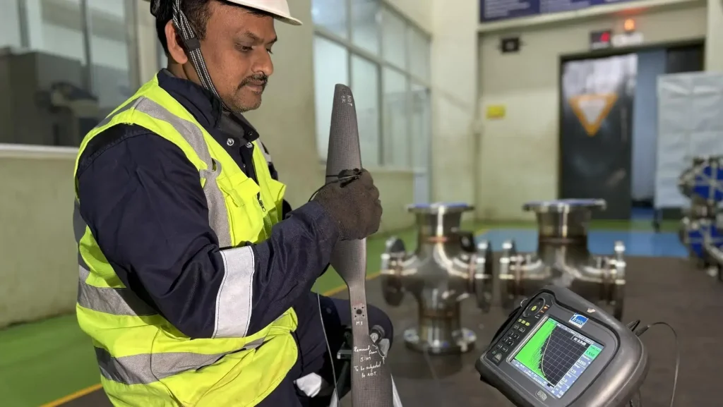
Ultrasonic testing (UT) is a non-destructive testing method that sends high-frequency sound waves into a material and analyses the returning echoes to find internal flaws such as cracks, porosity, inclusions, lack of fusion and laminations, and to measure thickness, without damaging the part.
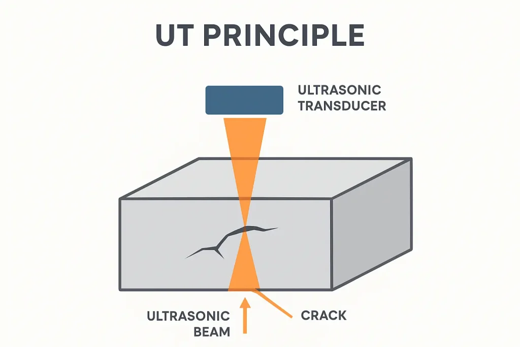
A piezoelectric probe transmits short pulses into the component through a couplant. Sound reflects from the back wall and from any discontinuity in its path. The flaw detector measures each echo’s arrival time and amplitude. Because the sound velocity in the material is known, the instrument calculates the depth of a flaw, and the echo amplitude indicates its size compared with a reference reflector. Industrial UT commonly uses frequencies from about 0.5 MHz to 15 MHz, with higher frequencies for thin sections and fine-grained material.
Ultrasonic testing services at a glance
| Service | What we inspect | Typical standards | Where |
|---|---|---|---|
| UT of weld joints | Butt, T and nozzle welds in pressure vessels, piping, tanks and structures | ASME V Art. 4, ISO 17640 / 11666, AWS D1.1 | Lab and on-site |
| UT of castings | Steel, aluminium and magnesium castings | ASTM A609, EN 12680-1 | Lab; foundry site on request |
| UT of forgings | Shafts, rings, discs, blocks and bars | ASTM A388, ASTM A745, EN 10228-3/-4 | Lab and on-site |
| UT of plates and bars | Rolled steel plate, flats, bars and rounds | ASTM A435, A578, A577, EN 10160 | Lab and on-site |
| Thickness gauging | Pipes, tanks, boiler tubes, chimneys, vessels | Customer procedure, ASME V | On-site and lab |
| PAUT and TOFD | Welds, corrosion mapping, crack sizing | ISO 13588, ISO 10863, ASME V | Lab and on-site |
| Composite dry-scan UT | Aerospace composites and bonded structures | Customer / OEM specification | Lab |
Standards shown are examples. We test to your specification, procedure or third-party requirement.
Ultrasonic Testing of Weld Joints (UT of Welds)
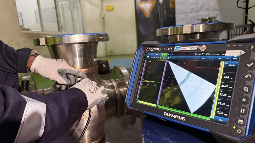
Angle-beam (shear wave) ultrasonic testing is the standard volumetric method for finding lack of fusion, lack of penetration, cracks, slag and porosity in welded joints. Our Level II inspectors scan welds in pressure vessels, piping, tanks and structural steelwork to your code, calibrate on side-drilled-hole reference blocks to draw the distance amplitude correction (DAC) curve, and evaluate indications for acceptance. Our in-house ASNT Level III approves the results, and we regularly work under third-party inspection.
How weld UT is done
- Clean the weld and base-metal surfaces over the full probe travel (skip) distance so the probe moves smoothly
- Select probe angle and frequency for the thickness and joint type
- Calibrate range and sensitivity and draw the DAC curve on reference blocks
- Scan the weld from both sides where access allows, and along the weld
- Locate, size and record indications: position, depth, length and amplitude
- Evaluate against the acceptance criteria; the Level III reviews and approves
- Issue the report
Codes we apply to weld UT
- ASME Section V, Article 4 for the technique, with acceptance criteria from the construction code (for example ASME Section VIII Division 1, Appendix 12)
- ISO 17640 for techniques and testing levels, with ISO 11666 acceptance levels 2 and 3 (corresponding to ISO 5817 quality levels B and C)
- AWS D1.1 for structural steel groove welds
- Customer or third-party inspector specifications
What weld UT covers, and what needs another method
Full-penetration butt welds are the easiest joints to test. T-joints, corner joints and nozzle or branch welds can also be tested, subject to geometry and access. ISO 17640 is written for fusion-welded joints of 8 mm thickness and above in ferritic steel with low attenuation. Thinner welds, austenitic stainless steel, dissimilar-metal welds and partial-penetration joints need a specific procedure (ISO 22825 covers welds in austenitic steel and nickel alloys) or another method such as radiography, phased array UT or TOFD. Where a code allows, UT is increasingly used instead of radiography because it has no radiation hazard and gives flaw depth and size. Download the free AWS D1.1 UT procedure for welds.
Ultrasonic Testing of Castings (UT of Castings)
Ultrasonic testing finds internal shrinkage cavities, gas porosity, inclusions and cracks in castings that cannot be seen on the surface. We test steel, aluminium and magnesium castings in the as-cast or heat-treated condition, so foundries can use the results for process control as well as acceptance.
Standards for casting UT
ASTM A609/A609M covers carbon, low-alloy and martensitic stainless steel castings. Procedure A calibrates on flat-bottom-hole reference blocks, and Procedure B calibrates on back-wall reflection. EN 12680-1 covers steel castings for general purposes. Aerospace and other castings are tested to the customer or OEM specification.
Practical points for foundries and buyers
- Rough as-cast surfaces reduce coupling, and light grinding or machining of the scan areas improves reliability.
- Coarse-grained castings scatter sound, so we use lower-frequency, larger-diameter probes where needed.
- Complex shapes need a scan plan so every critical section is covered.
- Ultrasonic testing and radiography are not directly comparable, so many specifications combine UT with radiography and magnetic particle testing for surface and near-surface flaws.
We test castings at our Peenya laboratory and, on request, at your foundry.
Ultrasonic Testing of Forgings (UT of Forgings)
Forgings such as shafts, rings, discs, blocks and bars are tested ultrasonically to find internal discontinuities (inclusions, cracks, bursts, shrinkage-related piping and hydrogen flakes) that can start fatigue failures in service. We test to ASTM A388/A388M for heavy steel forgings using DAC or DGS reference methods, and to your customer specification.
Standards for forging UT
- ASTM A388/A388M: ultrasonic examination of steel forgings
- ASTM A745/A745M: ultrasonic examination of austenitic steel forgings
- EN 10228-3 (ferritic and martensitic forgings) and EN 10228-4 (austenitic and austenitic-ferritic stainless forgings)
How forgings are scanned
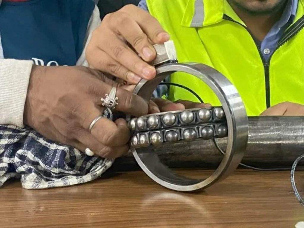
Straight-beam scans are made from the accessible faces while the back-wall echo is monitored for loss caused by internal flaws or attenuation. Angle-beam scans are added on rings and hollow sections where the specification requires. Indications are recorded by depth, amplitude and equivalent reflector size. Scan surfaces should be machined or ground smooth, and testing is normally carried out after final heat treatment.
Ultrasonic Testing of Steel Plates and Bars
Laminations run parallel to the rolled surface and can cause failures in pressure vessels and structures, so plate for critical service is tested before fabrication. We perform straight-beam scanning to ASTM A435/A435M and ASTM A578/A578M (three acceptance levels for special applications), with ASTM A577/A577M angle-beam examination as a supplement for non-laminar discontinuities, and to EN 10160 or your specification. Bars and rounds are tested for internal defects along their length. Our reference blocks and calibration standards give traceable and defensible results.
More Ultrasonic Testing Services
Ultrasonic thickness gauging and corrosion assessment
Digital ultrasonic thickness gauges measure remaining wall thickness on pipes, tanks, boiler tubes, chimneys and pressure vessels, so you can schedule maintenance and assess fitness for service. High-temperature probes and couplants allow measurement on hot surfaces such as boiler and heat-exchanger tubes. Gauge display resolution can reach 0.001 mm; measurement accuracy depends on the gauge, probe, surface condition, temperature and calibration on reference blocks. Ultrasonic thickness gauging service →
Phased array (PAUT) and TOFD
When the code or the job needs imaging, accurate sizing or a permanent digital record, we use Phased Array UT (PAUT) and Time of Flight Diffraction (TOFD) to ISO 13588, ISO 10863 and ASME Section V. PAUT gives sectorial and linear scans of the weld volume; TOFD gives accurate through-wall height sizing of planar flaws.
Aerospace composites and metallic components
Composites are inspected with dry-scan ultrasonic equipment that needs no messy couplant, using through-transmission or pulse-echo as the specification requires, to find delaminations, voids, inclusions and cracks. We keep composite calibration samples with artificial flaws to set up the equipment, and we test aluminium, magnesium and titanium components to aerospace specifications. Composite UT for aerospace →
IBR-approved ultrasonic testing for boilers
We are an approved ultrasonic inspection agency under the Indian Boiler Regulations (IBR) by the Inspector of Boilers, Karnataka, covering boiler drums, tubes and components. View our accreditations →
Codes and Standards for Ultrasonic Testing
You can choose any recognised standard or supply your own procedure. If you want help selecting the technique or writing a UT procedure and acceptance criteria, our ASNT Level III consultants can prepare one.
| Product or purpose | Standards | Notes |
|---|---|---|
| Weld UT: technique | ASME Section V Article 4 · ISO 17640:2018 · ASTM E164 (contact UT of weldments) · AWS D1.1 · ISO 22825 (austenitic steel and nickel-alloy welds) | ISO 17640 applies to fusion-welded joints ≥8 mm in ferritic steel with low attenuation |
| Weld UT: acceptance | ISO 11666:2018 (levels 2 and 3) · ASME VIII Div. 1 Appendix 12 · AWS D1.1 · ISO 23279 (characterisation) | ISO 11666 levels 2 and 3 correspond to ISO 5817 quality levels B and C |
| PAUT and TOFD of welds | ISO 13588 (PAUT) · ISO 10863 (TOFD) · ASME V Article 4 appendices | See the PAUT and TOFD pages |
| Castings | ASTM A609/A609M · EN 12680-1 | A609 has two calibration procedures (A and B) |
| Forgings | ASTM A388/A388M · ASTM A745/A745M · EN 10228-3 · EN 10228-4 | A745 and EN 10228-4 for austenitic grades |
| Plates | ASTM A435/A435M · A578/A578M · A577/A577M · EN 10160 | A435 and A578 straight-beam; A577 angle-beam supplement |
| Wrought products and bars | ASTM E2375 · ASTM E114 (straight-beam contact) · ASTM E587 (angle-beam contact) | Practices for developing procedures |
| General principles and setup | ASME V Article 5 · ISO 16810 · ISO 16811 | Sensitivity and range setting |
| Personnel and laboratory | ASNT SNT-TC-1A · ISO 9712 · ISO/IEC 17025:2017 · IBR 1950 | Personnel qualification, laboratory competence and boiler approval |
Standards are revised regularly. Confirm the edition your contract requires, or ask our Level III team.

NABL Accreditation, People and Equipment
| Item | Detail |
|---|---|
| Accreditation | NABL accredited to ISO/IEC 17025:2017 for the non-destructive testing discipline, covering permanent-laboratory and on-site testing as stated on the certificate. Download the certificate and scope. |
| Level II inspectors | UT Level II personnel qualified to ASNT SNT-TC-1A and ISO 9712, with on-the-job training at Trinity Institute of NDT Technology |
| Level III review | In-house ASNT NDT Level III approves the technique, procedure, calibration status, acceptance criteria and results for each project |
| Equipment | Digital A-scan flaw detectors with DAC and DGS/AVG evaluation and AWS D1.1 indication rating; portable units for on-site work; normal-beam, angle-beam and dual-element probes; high-temperature probes; PAUT and TOFD systems; dry-scan setup for composites; digital thickness gauges |
| Calibration | Reference and calibration blocks including side-drilled-hole blocks for DAC. Equipment is calibrated on a daily basis before use, and the Level III checks calibration status. |
| Approvals | IBR-approved ultrasonic inspection agency (Inspector of Boilers, Karnataka). Approved supplier to leading manufacturers including GAIL India, HAL, BEL, Siemens and GE. |
| Procedures | Approved NDT procedures, or your customer-specific UT procedure. Download a free sample UT procedure. |
Stainless steel and other coarse-grained materials scatter sound, so our inspectors use low-frequency, larger-diameter probes for these components.
How an Ultrasonic Testing Job Works at Trinity NDT
- Send your enquiry by WhatsApp, phone or email with the drawing, material, size, quantity and standard
- Receive a quotation, typically within two hours of receiving complete details
- Confirm with a purchase order and share any third-party inspection requirement
- Level III review of the technique, procedure and acceptance criteria
- Surface preparation and calibration on reference blocks
- Scanning in our laboratory or at your site, with third-party witness if required
- Evaluation and Level III approval of every indication
- Report issued with digital data for PAUT and TOFD jobs
What we need for your quote
- Component drawing or sketch, and product form (weld, casting, forging, plate, bar, tube)
- Material grade, dimensions, thickness and weight, and quantity
- Standard, specification and acceptance level, or your UT procedure
- Surface condition and access
- Location (our lab or your site) and any third-party inspection or witness requirement
- Delivery deadline
In our lab or at your site
You can bring parts to our facility in the 4th Phase of Peenya Industrial Area, or we can mobilise portable A-scan, PAUT and thickness-gauging equipment to your workshop, foundry, plant or installation. Our Level II inspectors are stationed to reach Bangalore, Hosur and Mysuru quickly, and we travel across India for larger projects.
What Is in Our Ultrasonic Testing Report
- Customer, job and part identification, material and thickness
- Standard, procedure number and acceptance criteria applied
- Equipment, probe details (frequency, size and angle), couplant and calibration blocks used, with calibration date
- Sensitivity or DAC/DGS setting and the scan plan or coverage
- Results for each recordable indication: location, depth, length and amplitude or equivalent size
- Acceptance evaluation (accept or reject) against the stated criteria
- Inspector name and certification level, and NDT Level III review and approval
What Ultrasonic Testing Can and Cannot Detect
UT is most sensitive to planar flaws that lie across the sound beam. It can miss flaws that run parallel to the beam and flaws very close to the scanned surface (the near-surface dead zone). Rough surfaces, coarse-grained material, very thin sections and complex geometry limit reliability, and the method needs a couplant and a skilled operator.
Best practice is to combine methods. Surface techniques such as dye penetrant, magnetic particle and eddy current testing catch what UT may miss near the surface, while UT and radiography examine the interior.
Advantages of ultrasonic testing
- Detects internal flaws with high sensitivity and measures their depth
- Needs access to one side only when using pulse-echo
- No radiation hazard, and portable equipment for on-site work
- Fast, and suited to automation; works on metals and many non-metals
- Also measures thickness for corrosion monitoring
UT compared with other NDT methods
| Feature | UT | Radiography (RT) | Magnetic particle (MT) | Dye penetrant (PT) | Eddy current (ET) |
|---|---|---|---|---|---|
| Internal flaws | Yes | Yes | No | No | No |
| Surface-breaking flaws | Limited near the surface | Limited | Yes (ferromagnetic) | Yes (non-porous) | Yes (conductive) |
| Flaw depth and height | Yes | Not directly | No | No | Limited |
| Thickness measurement | Yes | Limited | No | No | Limited (coatings, thin walls) |
| Radiation hazard | None | Yes | None | None | None |
| Access | One side (pulse-echo) | Both sides | Surface | Surface | Surface |
| Material limits | Coarse grain and rough surfaces reduce reliability | Most materials | Ferromagnetic only | Non-porous only | Conductive only |
| Best for | Welds, castings, forgings, plate, thickness | Complex geometry and volumetric records | Fast surface crack screening | Surface cracks on non-magnetic metals | Tubes, sorting, surface cracks |
Not sure which method your specification needs? Ask our ASNT Level III team.
Ultrasonic Testing Charges and Turnaround
We quote after reviewing your drawing, standard and quantity, so the price reflects the actual scope. The main cost drivers are:
- Technique: conventional UT, PAUT, TOFD, thickness gauging or composite dry-scan
- Product form, size, weight, thickness and number of components or weld length
- Standard and acceptance level, and the amount of reporting required
- Surface condition and access
- Testing in our lab or at your site (mobilisation and travel)
- Third-party witnessing and urgency
Lab jobs are scheduled as soon as parts and the purchase order are received. We confirm the date when we quote, and urgent jobs can be prioritised. Request a quotation on WhatsApp
Why Customers Choose Trinity NDT for Ultrasonic Testing
- Accredited laboratory. NABL ISO/IEC 17025:2017 accreditation for NDT, an IBR approval for boiler UT and 25 years of experience since 2001.
- Level III oversight on every project. The in-house ASNT Level III reviews the technique and approves results, which is why customers and third-party agencies accept our reports.
- Complete UT range. Conventional UT of welds, castings, forgings and plates, thickness gauging, PAUT, TOFD and composite dry-scan.
- All methods on one campus. RT, MT, PT, ET, PMI and visual testing alongside UT, so one supplier can close out a component.
- Lab or on-site. Portable equipment and Level II inspectors stationed for Bangalore, Hosur and Mysuru.
How to choose an ultrasonic testing lab: checklist
- Does the accreditation scope list ultrasonic testing, the technique and the standard you need?
- Who qualifies and approves the results: Level II inspectors, and a Level III for procedures and final approval?
- Which personnel scheme applies (ASNT SNT-TC-1A, ISO 9712) and does your specification accept it?
- How are equipment and blocks calibrated, and how often?
- Will the report state the standard, acceptance level, probe details and every recorded indication?
- Can the lab work on site and under third-party witnessing?
- Can the same lab do surface NDT and radiography if the specification needs more than UT?
Ultrasonic Testing Techniques We Use
Pulse-echo (single probe)
One probe transmits a pulse and receives the echoes. The time between transmission and echo gives the depth of a flaw or the back wall, and the echo amplitude indicates its size. It needs access to one side only, and is the basis for most weld, casting, forging, plate and thickness testing.
Angle-beam (shear wave)
A probe on a wedge sends sound into the material at a set angle (commonly 45°, 60° or 70°). It is the standard technique for welds and for flaws that a straight beam cannot reach. Skip distance and beam path length are used to locate indications, and the DAC curve sets the evaluation sensitivity.
Through-transmission
A transmitting probe on one side and a receiving probe on the opposite side measure how much sound gets through. Flaws cast an acoustic shadow. It suits composites, bonded structures and highly attenuating materials. It needs access to both sides and does not give flaw depth.
Phased array UT (PAUT)
A multi-element probe steers and focuses the beam electronically to produce sectorial and linear images of the weld volume, with a permanent digital record. Phased array UT service →
Time of flight diffraction (TOFD)
Two probes on opposite sides of a weld detect diffracted signals from flaw tips, giving accurate through-wall height sizing of planar flaws. Near-surface and back-wall zones need supplementary techniques. TOFD ultrasonic service →
Industries and Service Area
We test for aerospace, automotive, manufacturing, oil and gas, power generation, construction and shipbuilding customers, and for foundries, forge shops, boiler makers and pressure-vessel fabricators.
Our laboratory is at 491, Site No. 12, 14th Cross, 4th Phase, Peenya Industrial Area, Bangalore 560058. On-site teams serve Bangalore (Peenya, Yeshwanthpur, Rajajinagar, Bommasandra, Jigani and the Tumakuru Road corridor), Hosur, Mysuru and locations across India.
Related NDT services
Radiographic testing · Magnetic particle testing · Dye penetrant testing · Eddy current testing · PMI testing · Advanced NDT (PAUT, TOFD, CR) · Aerospace NDT · Material testing
UT training
Looking for Level I or II certification? See our ultrasonic testing training courses and ultrasonic thickness gauging course, offered to ASNT SNT-TC-1A and ISO 9712 schemes.
Request an Ultrasonic Testing Quotation
Send the drawing, material, quantity and standard and we will confirm the technique and price.
WhatsApp: +91 98441 29439 Call +91 98441 29439 info@trinityndt.com
Trinity NDT WeldSolutions Private Limited
491, Site No. 12, 14th Cross, 4th Phase, Peenya Industrial Area, Bangalore 560058, Karnataka, India
Technically reviewed by Ravi Kumar T, CEO and Co-Founder, Trinity NDT WeldSolutions Pvt. Ltd. (ASNT NDT Level III in six NDT methods, International Welding Engineer). Last reviewed: 21 September 2026. Standards references are checked against ASTM, ISO and ASME publications. Always confirm the edition your contract requires.
Frequently Asked Questions About Ultrasonic Testing
What is ultrasonic testing (UT)?
Ultrasonic testing (UT) is a non-destructive testing method that sends high-frequency sound waves into a material and analyses the returning echoes to find internal flaws such as cracks, porosity, inclusions, lack of fusion and laminations, and to measure thickness, without damaging the part. The depth of a flaw is calculated from the echo's arrival time, and its size is estimated from the echo amplitude.
Is your ultrasonic testing lab in Bangalore NABL accredited?
Yes. Trinity NDT's laboratory in Peenya, Bangalore is accredited by NABL to ISO/IEC 17025:2017 for non-destructive testing, covering permanent-laboratory and on-site testing. The accredited scope, including the ultrasonic testing techniques, materials and standards covered, can be downloaded from our website. Ask us to confirm that your specific technique and standard are within scope.
What defects can ultrasonic testing detect?
UT detects internal and sub-surface flaws including cracks, lack of fusion, lack of penetration, slag inclusions, porosity, shrinkage cavities, laminations, delaminations in composites and bond defects. It is most sensitive to planar flaws that lie across the sound beam. It is less reliable for flaws parallel to the beam or very close to the scanned surface, which are better found by surface methods.
How is ultrasonic testing of weld joints done and which standards apply?
Weld UT normally uses angle-beam (shear wave) probes calibrated on side-drilled-hole blocks to draw a DAC curve. The weld is scanned from both sides where possible, and indications are located, sized and evaluated. Common standards are ASME Section V Article 4, ISO 17640 with ISO 11666 acceptance levels, and AWS D1.1, with acceptance criteria taken from the construction code or your specification.
How do you perform ultrasonic testing of castings?
Castings are scanned with straight-beam probes, and angle-beam probes where required, to find shrinkage, porosity, inclusions and cracks. For carbon, low-alloy and martensitic stainless steel castings the common standard is ASTM A609/A609M, which has two calibration procedures. EN 12680-1 covers steel castings for general purposes. Rough surfaces and coarse grain reduce reliability, so scan areas are prepared and probes are chosen to suit the grain.
How do you perform ultrasonic testing of forgings?
Forgings such as shafts, rings, discs and blocks are scanned with straight-beam probes from accessible faces while the back-wall echo is monitored, with angle-beam scans added where the specification requires. Indications are recorded by depth, amplitude and equivalent reflector size using DAC or DGS methods. Common standards are ASTM A388/A388M, ASTM A745/A745M for austenitic steel and EN 10228-3 and -4.
Can ultrasonic testing be used on stainless steel and austenitic welds?
Yes, but stainless steel has a coarse grain structure that scatters and attenuates sound, so standard weld procedures written for ferritic steel are not enough. We use lower-frequency, larger-diameter probes and a specific procedure, and for austenitic and dissimilar-metal welds we may recommend PAUT or radiography. ISO 22825 covers ultrasonic testing of welds in austenitic steel and nickel alloys.
What is the minimum thickness for ultrasonic testing of welds?
ISO 17640 is written for manual UT of fusion-welded joints of 8 mm thickness and above in low-attenuation ferritic steel. Thinner welds can be tested only with a special procedure agreed with the customer or a standard that covers them, and radiography, PAUT or another method may suit better. Tell us the thickness and code and we will recommend the technique.
Is ultrasonic testing better than radiography?
Neither is better in every case. UT finds planar flaws such as cracks and lack of fusion, measures flaw depth, needs access to one side only and has no radiation hazard. Radiography gives a permanent image and suits complex geometry and volumetric flaws. Where the code allows, UT, PAUT and TOFD increasingly replace radiography on welds, and many specifications combine methods.
What is the difference between UT, PAUT and TOFD?
Conventional UT uses a single-element probe and an A-scan display and depends on operator interpretation. Phased array UT (PAUT) uses a multi-element probe to steer and focus the beam electronically and produces images with a digital record. Time of flight diffraction (TOFD) uses two probes and flaw-tip diffraction to size the through-wall height of planar flaws accurately.
Can ultrasonic testing find surface cracks?
Conventional UT is not the best method for surface-breaking or very near-surface cracks because of the near-surface dead zone and the orientation of such flaws. Dye penetrant testing suits non-porous materials, magnetic particle testing suits ferromagnetic materials and eddy current testing suits conductive materials. Many specifications combine one of these surface methods with UT or radiography for full coverage.
Do you provide on-site ultrasonic testing?
Yes. We test in our Peenya laboratory and at customer sites, using portable A-scan, PAUT and thickness-gauging equipment. Our Level II inspectors are stationed to serve Bangalore, Hosur and Mysuru quickly, and we travel across India for larger projects. On-site work uses the same procedures, calibration and Level III review as laboratory work.
How much does ultrasonic testing cost?
The cost depends on the technique, the product form, size, thickness and quantity, the standard and acceptance level, surface condition, reporting requirements, whether testing is in the lab or on site, and third-party witnessing. We quote after reviewing your drawing, standard and quantity so the price reflects the actual scope. Send the details on WhatsApp for a quotation.
How quickly can you provide a quotation and test results?
We typically reply with a quotation within two hours of receiving complete details on WhatsApp or email. Laboratory jobs are scheduled as soon as parts and the purchase order arrive, and we confirm the date when we quote. Urgent jobs can be prioritised. Report timing depends on quantity, size, standard and the report format required.
What information do you need to quote for ultrasonic testing?
Send the component drawing or sketch, product form (weld, casting, forging, plate or bar), material grade, dimensions and thickness, quantity, the standard, specification and acceptance level or your UT procedure, surface condition and access, whether testing is in our lab or at your site, any third-party inspection requirement, and your deadline.
What is included in an ultrasonic testing report?
A UT report identifies the job and part, the standard and acceptance criteria, the equipment, probe details and calibration blocks used, the sensitivity or DAC setting and scan coverage, and the results for each recordable indication including location, depth, length and amplitude. It states the accept or reject evaluation, the inspector's certification level and the Level III review and approval.
Can you test under third-party inspection or to customer specifications?
Yes. Our inspectors regularly work under third-party inspection and test to industry standards or to customer-specific UT procedures. Our in-house ASNT Level III reviews the technique, checks calibration status and acceptance criteria and approves results. We can also prepare a UT procedure tailored to your requirements through our Level III consulting service.
Do you provide IBR-approved ultrasonic testing for boilers?
Yes. Trinity NDT is an approved ultrasonic inspection agency under the Indian Boiler Regulations (IBR) by the Inspector of Boilers, Karnataka, covering boiler drums, tubes and components. Please share the IBR requirement and applicable form or certificate when you enquire so we can align the work and documentation.
Can you ultrasonically test composites and aerospace materials?
Yes. We use dry-scan ultrasonic equipment for composite materials, which needs no messy couplant, and we use through-transmission or pulse-echo as the specification requires to find delaminations, voids, inclusions and cracks. We keep composite calibration samples with artificial flaws, and we test aluminium, magnesium and titanium components to aerospace specifications.
Who performs and approves your ultrasonic testing?
Tests are performed by UT Level II inspectors qualified to ASNT SNT-TC-1A and ISO 9712, and monitored by in-house ASNT NDT Level III specialists. For each project the Level III reviews the technique and procedure, checks calibration status and acceptance criteria, and approves the results. Inspectors also receive on-the-job training at Trinity Institute of NDT Technology.
How accurate is ultrasonic thickness gauging?
Digital ultrasonic thickness gauges can display readings to 0.001 mm, but display resolution is not the same as accuracy. Accuracy depends on the gauge and probe, the surface condition, the temperature, the material's sound velocity and calibration on reference blocks. We calibrate before use and can measure hot surfaces such as boiler tubes using high-temperature probes and couplants.
Also see: UT Level II Training Course →
Ultrasonic Testing Principles (Complete Guide)
Understanding the Pulse Echo Technique
When you need to know what’s happening inside a material without cutting it open, that’s where the pulse echo technique comes in. It’s one of the most reliable methods we use in ultrasonic testing, and once you understand how it works, you’ll see why it’s become the industry standard.
How It Actually Works
Think of it like shouting in a canyon and listening for the echo. Our ultrasonic transducer sends a short burst of high-frequency sound waves into your material. These waves travel through the material until they hit something—maybe a crack, a void, or even just the back wall of the component. When they hit that boundary, some of the energy bounces back to the transducer, which now switches to “listening mode.”
The clever part? We measure the time it takes for that echo to return. Since we know how fast sound travels through your specific material (steel, aluminum, composites—they all have different speeds), we can calculate exactly how deep that defect is. It’s basic physics, but incredibly precise.
What We Can Tell You
The pulse echo technique gives us a complete picture of what’s going on inside your components:
Location and depth – We pinpoint exactly where defects are, down to millimeter accuracy. This isn’t guesswork; it’s measurement.
Size estimation – The strength and shape of the echo signal tells us roughly how large a defect is. Bigger flaws reflect more energy back.
Material thickness – Even on parts where you can only access one side, we can measure the total thickness by catching that back wall reflection.
Type of discontinuity – Experienced technicians can often identify whether they’re looking at a crack, inclusion, porosity, or delamination based on how the signal behaves.
Why Our Clients Choose This Method
You get access to both sides of the material in one test. While some techniques require you to position equipment on opposite sides of a component, pulse echo works from a single surface. That’s massive when you’re inspecting large structures, assembled equipment, or anything where access is limited.
The sensitivity is exceptional. We’re talking about finding defects that are a fraction of a millimeter in size—things you’d never see with your eyes or even basic testing methods.
And here’s what really matters: you get permanent records. We can save those waveforms, create detailed reports, and you’ll have documentation that stands up to any audit or regulatory requirement.
Real-World Applications
We use pulse echo for everything from checking welds on pressure vessels to inspecting aircraft components for fatigue cracks. It works on forgings, castings, plate material, and even composites. If you’re in aerospace, power generation, oil and gas, or manufacturing, chances are this technique is already specified in your inspection procedures.
The bottom line? Pulse echo ultrasonic testing gives you confidence that what you’re putting into service is safe, reliable, and meets specifications. No destruction, no guesswork—just solid data about the integrity of your materials.
Understanding the Through-Transmission Technique
Sometimes the best way to inspect a material is to send sound waves straight through it from one side to the other. That’s exactly what the through-transmission technique does, and for certain applications, it’s simply the most effective approach we have.
How the Method Works
Picture two transducers working as a team. We place one on each side of the material you need inspected—one acts as the transmitter, constantly sending ultrasonic waves through the component, while the other sits on the opposite side as the receiver, picking up whatever makes it through.
Here’s the key principle: when the material is sound and uniform, most of that ultrasonic energy passes straight through and arrives at the receiver with good strength. But when there’s a defect—a crack, void, inclusion, or delamination—it blocks or scatters those sound waves. The receiver picks up a weaker signal, or sometimes nothing at all. That drop in signal strength tells us there’s something wrong in the path between those two transducers.
We’re essentially creating a shadow. Any flaw in the material casts an “acoustic shadow,” and we can map out exactly where those shadows appear.
What This Technique Reveals
Defect detection – We excel at finding discontinuities that lie perpendicular to the sound beam. Delaminations in composites, large voids, and inclusions show up clearly because they interrupt that straight-line transmission path.
Uniformity verification – You get a clear picture of whether your material has consistent properties throughout. Variations in density, porosity, or bonding quality all affect how much sound energy makes it through.
Large area scanning – Because we’re measuring what gets through rather than waiting for echoes, we can often scan faster, especially when you’re checking big, flat components like composite panels or bonded assemblies.
Where Through-Transmission Shines
This technique really proves its worth with specific materials and geometries. Composite structures in aerospace? Through-transmission is often the go-to method. Those layered materials can be tricky with pulse echo techniques, but through-transmission cuts right through the complexity.
Bonded assemblies are another sweet spot. When you’ve got adhesive joints or brazed connections, you need to verify that bond integrity. Through-transmission lets us confirm that energy is transferring properly across those interfaces—a strong indicator that the bond is solid.
We also use it extensively for thin materials where pulse echo might struggle to separate signals, and for parts with complex geometries where getting a good echo back would be challenging. And when you’re dealing with highly attenuative materials that absorb ultrasonic energy quickly, through-transmission can still get reliable results because we’re measuring transmitted energy rather than relying on weak echoes.
The Practical Considerations
Let’s be straight about what this method requires: you need access to both sides of the component. That’s non-negotiable. For assembled equipment, in-service structures, or anything where you can only reach one surface, through-transmission simply won’t work. But when you do have that access, the results are excellent.
The setup takes a bit more coordination than single-sided techniques. You’re aligning two transducers and maintaining that alignment as you scan. For automated systems, we’ve got this down to a science. For manual inspection, it requires skilled technicians who know how to maintain proper positioning.
One thing to understand: while through-transmission is outstanding at detecting defects, it doesn’t directly tell you the depth of a flaw within the material. You know something’s there because the signal dropped, and you know its lateral position, but pinpointing exactly how deep it sits requires additional analysis or complementary testing methods.
Why Companies Rely on This Approach
When you’re manufacturing critical composite components or assembling bonded structures, through-transmission gives you confidence in the final product. It’s particularly valuable in production environments where you’re checking part after part and need consistent, reliable detection of delaminations or bond failures.
The aerospace industry has relied on this technique for decades, and for good reason. When structural integrity is non-negotiable and you’re working with advanced materials, through-transmission provides the assurance you need. It’s written into countless specifications and quality procedures precisely because it works.
Bottom line: if you can access both sides of your component and you need to verify material uniformity or detect planar defects, through-transmission ultrasonic testing delivers clear, dependable results that keep your operations safe and compliant.
Understanding Phased Array Ultrasonic Testing (PAUT)
If conventional ultrasonic testing is like using a flashlight, phased array is like having a spotlight with full control over where it points, how it focuses, and how wide the beam spreads. It’s a game-changer in non-destructive testing, and once you see what it can do, you’ll understand why it’s become the preferred method for so many critical inspections.
How Phased Array Technology Works
Instead of using a single crystal transducer that sends out one fixed beam, phased array probes contain multiple small elements—sometimes 16, 32, 64, or even more—all arranged in a line or matrix. Here’s where it gets interesting: we can fire these elements individually with precise timing delays between them.
By controlling when each element pulses, we literally steer and shape the ultrasonic beam electronically. Want to inspect at a 45-degree angle? Done. Need to sweep through multiple angles without moving the probe? Easy. Want to focus the beam at a specific depth? Just adjust the timing sequence. It’s all software-controlled, which means we have incredible flexibility without ever repositioning the probe.
Think of it like a stadium doing “the wave.” When each section stands up at just the right moment, you create a wave that travels around the stadium. Our phased array elements work the same way—precise timing creates a steerable, focusable ultrasonic beam.
What PAUT Brings to Your Inspection
Complete volumetric coverage – We can inspect an entire weld or component volume from a single probe position. The beam sweeps through multiple angles, giving us a complete picture of what’s inside. You’re not missing anything because of limited beam angles.
Real-time imaging – Instead of just seeing A-scan waveforms, you get actual cross-sectional images of your component. B-scans show you a side view slice through the material, C-scans give you a top-down map, and S-scans display the data along the actual surface contour. It’s visual, intuitive, and you can spot defects immediately.
Precise defect characterization – We’re not just detecting flaws; we’re measuring them accurately. Length, height, orientation, position—phased array gives us detailed dimensional information that helps you make informed decisions about repair or rejection.
Faster inspections – Because we’re covering multiple angles and positions simultaneously, inspections that used to take hours can now be completed in a fraction of the time. For production environments or turnaround situations where time is money, this efficiency is massive.
Permanent digital records – Every scan gets saved with complete imaging data. You can review it later, compare it to future inspections, and you’ve got documentation that satisfies the most demanding quality requirements.
Where PAUT Excels
Weld inspection is where phased array really shows its strength. Complex weld geometries, thick sections, dissimilar metal welds—these are all situations where conventional UT struggles but PAUT thrives. We can inspect the entire weld volume, detect and size defects accurately, and do it faster than traditional methods.
For corrosion mapping, phased array is unbeatable. We create detailed thickness maps of pipes, pressure vessels, and storage tanks, showing you exactly where material loss is occurring. You get color-coded maps that make it easy to identify problem areas and plan your maintenance strategy.
Crack detection is another strong suit. Whether it’s fatigue cracks in aircraft components, stress corrosion cracking in petrochemical equipment, or service-induced cracking in power generation systems, PAUT finds them and sizes them with precision.
We also use it extensively for manufacturing inspection of aerospace components, turbine parts, and any critical component where conventional testing just doesn’t provide enough information.
The Real-World Advantages
Access is often limited in industrial settings. With phased array, we can inspect from one side and still get complete coverage. The electronic beam steering means we’re not trying to squeeze conventional probes into impossible positions or compromising inspection quality because we can’t get the right angle.
The inspection data we provide is clear and defensible. When you’ve got regulators, customers, or internal quality teams asking questions, those color-coded sectional images speak for themselves. There’s no interpretation debate—everyone can see exactly what’s there.
For companies with ongoing integrity management programs, phased array creates a digital baseline. You can track changes over time, identify degradation trends, and move from reactive maintenance to predictive strategies. That’s not just good engineering; it’s smart business.
The Level of Expertise Required
Here’s something important: phased array is a sophisticated technique that demands proper training and certification. Our technicians undergo extensive training beyond conventional Level II certification. They need to understand beam physics, setup parameters, focal laws, and data interpretation. When you’re getting a phased array inspection from us, you’re getting genuinely skilled professionals who know this technology inside and out.
The equipment is advanced, but in the right hands, it’s also incredibly reliable. Modern phased array systems have built-in calibration verification, setup validation, and quality checks that ensure consistent results.
Why Forward-Thinking Companies Choose PAUT
Industries that can’t afford failures—aerospace, nuclear power, oil and gas, pipeline operators—have made phased array their standard. It’s not just about meeting code requirements anymore; it’s about having the best possible information to make risk-based decisions.
When you’re evaluating the integrity of critical infrastructure, you want imaging, not just signals. You want detailed defect characterization, not just detection. You want inspection speed that minimizes downtime without sacrificing quality. That’s exactly what phased array ultrasonic testing delivers.
If your inspection challenges involve complex geometries, limited access, demanding codes, or simply the need for better information to support critical decisions, phased array is the answer. It’s the technology that brings ultrasonic testing into the modern era.
Understanding Time of Flight Diffraction (TOFD)
When you need absolute certainty about defect sizing—especially crack height measurement—Time of Flight Diffraction stands in a class of its own. While other ultrasonic techniques are excellent at finding defects, TOFD is the method you turn to when accurate dimensional information isn’t just nice to have, it’s critical for fitness-for-service decisions.
How TOFD Actually Works
The physics behind TOFD is elegant. We use two angled probes positioned on opposite sides of the weld or inspection area. One probe transmits ultrasonic waves, and the other receives them. But here’s what makes TOFD different: we’re not looking for reflections from the face of a defect like conventional UT does. Instead, we’re detecting diffracted signals from the tips of defects.
When an ultrasonic wave hits the sharp edge of a crack or other discontinuity, it diffracts—meaning it scatters in all directions, including back toward our receiving probe. We get diffracted signals from both the top tip and bottom tip of any defect that’s there. By precisely measuring the time difference between when these signals arrive, we calculate the exact height of that defect.
Think of it like triangulation, but with sound waves and time. The geometry is fixed, we know the sound velocity in the material, and we’re measuring time differences down to nanoseconds. That combination gives us remarkably accurate depth and height measurements.
What Makes TOFD Special
Exceptional height sizing accuracy – This is TOFD’s superpower. We can measure crack heights to within a millimeter or better, even in thick sections. When you’re doing engineering critical assessments or fitness-for-service evaluations, that accuracy is everything. You’re making decisions about whether something can safely remain in service, and TOFD gives you the reliable data to support those decisions.
Through-thickness coverage – From the top surface to the back wall, TOFD inspects the entire thickness of the material in one pass. You’re getting volumetric inspection with a single probe setup, which means efficiency without compromising coverage.
Excellent crack detection – Because we’re detecting diffraction from crack tips rather than reflections from crack faces, TOFD is particularly good at finding planar defects. Even tight cracks that might not reflect much energy back to a conventional probe will diffract signal from their tips.
Less sensitive to defect orientation – Conventional UT can miss defects if they’re not oriented to reflect sound back to the probe. TOFD doesn’t have that limitation to the same degree. If there’s a crack tip in the inspection zone, we’re getting diffracted signal from it regardless of the defect’s precise orientation.
Permanent digital record – Every TOFD scan creates a detailed D-scan image showing the cross-section of your weld or component. These images are archived, reviewable, and provide an indisputable record of what was found and where.
Where TOFD Proves Its Worth
Pressure vessel and pipeline weld inspection is where you’ll find TOFD used most extensively. These are high-consequence assets where defect sizing isn’t optional—it’s mandated by codes and regulations. ASME, API, and various international standards recognize TOFD as a preferred or required technique for good reason.
For crack monitoring in operating equipment, TOFD is invaluable. You can establish a baseline measurement, then track crack growth over time during subsequent inspections. That growth rate data informs your inspection intervals and helps you predict remaining service life.
Thick section welds are another natural fit. When you’re dealing with materials 25mm, 50mm, or even thicker, conventional techniques start struggling with penetration and dead zones. TOFD handles thick sections with ease, maintaining its sizing accuracy throughout the full thickness.
We also use it extensively for dissimilar metal welds, corrosion-resistant alloy overlays, and any situation where you need defensible defect sizing for fitness-for-service calculations.
The Technical Advantages
TOFD gives you information that other techniques simply can’t match. The lateral wave that travels along the surface provides a precise time reference. The backwall reflection confirms you’ve got coverage through the entire thickness. And those diffracted signals from defect tips give you exact through-thickness positioning.
The technique is highly repeatable. When different technicians inspect the same area, or when you come back months or years later for a follow-up inspection, you get consistent results. That repeatability is crucial for crack growth monitoring and trending analysis.
Detection sensitivity is impressive—we’re finding defects down to 1-2mm in height depending on the material and inspection setup. But more importantly, once we’ve detected something, we’re sizing it accurately. That’s the real value proposition.
Understanding the Limitations
TOFD isn’t perfect for everything, and it’s important to know where it works best. Near-surface detection has a blind zone—typically the upper few millimeters of material where the lateral wave obscures any defect signals. For near-surface inspection, we typically supplement TOFD with pulse-echo or other techniques.
Similarly, there’s a small dead zone at the backwall where the backwall signal can mask small defects. Again, this is a known limitation that we work around by combining techniques when necessary.
TOFD also requires smooth, prepared surfaces for probe coupling and accurate probe positioning. You can’t just roll it across a rough, as-welded surface and expect good results. Surface preparation is part of the process.
And here’s something critical: TOFD data interpretation requires trained, experienced personnel. Those D-scan images aren’t always intuitive to read. Our technicians need specialized TOFD training and certification beyond basic ultrasonic qualifications.
Why Integrity Engineers Specify TOFD
When you’re responsible for asset integrity, you need data you can defend. TOFD provides exactly that—quantitative, accurate, reproducible defect measurements that stand up to scrutiny from regulators, insurers, and internal review.
For risk-based inspection programs, TOFD enables informed decision-making. Instead of automatically repairing every indication, you can accurately assess whether a defect is acceptable for continued service based on actual measured dimensions and fracture mechanics calculations.
The efficiency gains are real too. We cover large volumes quickly while maintaining high detection and sizing reliability. For turnaround situations where inspection time directly impacts downtime costs, that efficiency translates to significant savings.
The Bottom Line
Time of Flight Diffraction isn’t just another ultrasonic technique—it’s a precision measurement tool for critical applications. When codes require defect height sizing, when fitness-for-service assessments demand accurate data, when you’re monitoring crack growth in operating equipment, TOFD delivers the information you need to make confident, defensible decisions.
Combined with complementary techniques to address its near-surface and backwall limitations, TOFD provides comprehensive weld inspection that meets the most stringent industry requirements. It’s why major operators in oil and gas, power generation, and pressure vessel fabrication have made it their standard for critical weld inspection.
Comparision of Ultrasonic Testing Vs Other NDT methods
UT vs Other NDT Methods - Quick Comparison
| Feature | Ultrasonic Testing (UT) | Radiography (RT) | Magnetic Particle (MPI) | Eddy Current (ET) |
|---|---|---|---|---|
| Detects Internal Flaws | ✓ Excellent | ✓ Excellent | ✗ No | ✗ Surface Only |
| Detects Surface Flaws | ✓ Good | ✗ Limited | ✓ Excellent | ✓ Excellent |
| Flaw Depth Measurement | ✓ Yes (Accurate) | ✗ No | ✗ No | ✓ Limited |
| Thickness Measurement | ✓ Yes | ✗ No | ✗ No | ✓ Limited |
| Safety (No Radiation) | ✓ Safe | ✗ Radiation Hazard | ✓ Safe | ✓ Safe |
| Speed of Testing | ✓ Fast | ✗ Slow (Film Processing) | ✓ Very Fast | ✓ Very Fast |
| Portability | ✓ Portable | ✗ Heavy Equipment | ✓ Portable | ✓ Portable |
| Material Limitation | Metals & Non-Metals | All Materials | Ferromagnetic Only | Conductors Only |
| Best For | Welds, Thickness, Internal Flaws | Complex Geometry, All Materials | Surface Cracks, Fast Screening | Surface Cracks, Tubes, Conductivity |
Need help choosing the right NDT method? Contact our ASNT Level III experts →
Key Highlights
- NABL ISO17025:2017 Accreditation for NDT Services
- UT equipment with DGS, AVG, AWS flaw sizing for welds
- Range of probes for high temperature use
- UT technicians holds NDT Level II as per ASNT SNT TC 1A and ISO9712
- Experienced in house ASNT NDT Level III
- ASNT NDT Level III trainers for NDT Level 1, 2 courses on Ultrasonic testing.
- Download Free Sample Ultrasonic inspection procedure