
By Trinity NDT WeldSolutions Team | Published: May 2026 | Peenya, Bangalore
There are jobs in this work that go exactly as planned. You set up the equipment, run the procedure, the readings drop, and the component goes out the door. The client is happy, the report is signed, and you move on to the next job. We are about to know an interesting demagnetization case study.
And then there are days when a component gives you a fight.
Today was one of those days — and the component that decided to be stubborn was a steel shaft that arrived at our Peenya laboratory carrying over 10 Gauss of residual magnetism and an absolutely determined resistance to losing it.
This is the story of that shaft, how it got to 10 Gauss, why that is a serious problem for any rotating machine, and what it took to bring it back down below the 3 Gauss threshold that industry standards demand.
First — Why Was This Shaft Magnetised?
The client who brought this shaft to us had previously sent it for Magnetic Particle Inspection (MPI) at another facility. MPI — also called Magnetic Particle Testing (MPT) — is one of the most effective methods for detecting surface and near-surface cracks in ferromagnetic components. During MPI, a strong magnetic field is intentionally induced into the component using either a yoke, a prod, a coil, or a bench-type stationary machine. This magnetisation is what makes the test work — it creates the flux leakage that attracts magnetic particles to crack locations and makes them visible.
The problem is that steel has memory. When a magnetic field is applied and then removed, ferromagnetic materials do not simply return to a neutral state. They retain a portion of the induced magnetic field — what we call the residual magnetism or remnant field. In some steels — particularly high-carbon and alloy steels with high coercivity — this residual field can be surprisingly strong and surprisingly stubborn.
On this particular shaft, the MPI inspection had clearly been performed using a high-magnetisation technique. The resulting residual field measured over 10 Gauss on our calibrated digital Gaussmeter when the shaft arrived at our facility.
Why Does 10 Gauss Matter? Why Not Just Leave It?
This is a question we hear regularly. “It’s invisible. It doesn’t affect how the shaft looks. Why does it matter?”
The answer is: because residual magnetism causes damage in ways that are both subtle and accumulative. Let us walk through exactly what happens when a magnetised shaft enters service.
Bearing damage from arc discharge. In a rotating shaft running in electrical equipment, a residual magnetic field creates a voltage potential that can discharge through the bearing races as a tiny electrical arc — sometimes called Electrical Discharge Machining (EDM) pitting of the bearing. Over time, this pitting destroys bearing surfaces, increases noise and vibration, and eventually causes bearing failure. A shaft with 10 Gauss of residual magnetism in a motor or generator is a bearing damage accelerant.
Chip and swarf attraction in machining. If a magnetised shaft goes into a subsequent machining operation — grinding, turning, or polishing — it attracts metallic chips and swarf directly to the surface being machined. These particles become embedded in the surface or cause scoring. The machined finish is compromised, dimensional tolerances suffer, and the component may need to be scrapped.
Interference with precision instruments. Any precision measuring instrument — a CMM probe, a dial gauge, a digital calliper — that comes close to a strongly magnetised shaft will give false readings or suffer calibration drift. In a quality-controlled manufacturing environment, this is unacceptable.
Other Issues with Residual Magnetism
Welding arc blow. If a magnetised shaft or component is to be welded, residual magnetism causes arc blow — a deflection of the welding arc away from the intended joint. The result is poor fusion, irregular bead geometry, and increased weld defects. For shaft repair or hardfacing welding, demagnetisation before welding is a mandatory first step.
Compass and navigation interference. In marine, aviation, or defence applications, a magnetised component near a compass or navigation instrument can cause heading errors. This is not a theoretical risk — it is a documented failure mode in marine engineering.
For all of these reasons, the standard practice across industries — from automotive and power generation to aerospace and defence — is to specify a maximum residual field of 3 Gauss or less before a component is approved for final assembly or further processing. At 10 Gauss, this shaft was more than three times above the acceptable limit.
The Challenge — Why This Shaft Was Difficult
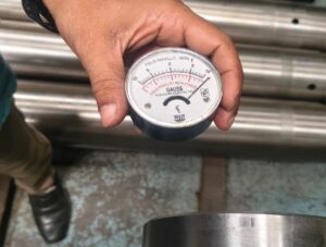
Image 1: Initial residual field measurement on the shaft — 10+ Gauss. The Gaussmeter probe is positioned at the shaft surface, showing the elevated reading that indicates significant retained magnetism from the previous MPI inspection.
When our Senior Demagnetization Technician first ran the Gaussmeter over the shaft, the reading was immediately concerning — not just for the magnitude, but for the distribution of the field. In a straightforward demagnetisation job, the residual field is fairly uniform across the component surface. You set up the coil, run the procedure, and the readings drop evenly.
This shaft was not straightforward.
The field was distributed asymmetrically across the shaft length — stronger at one end, relatively weaker at the midpoint, and elevated again at the other end. This told an experienced technician something specific: the MPI technique used at the other facility had likely involved multiple separate magnetisation shots at different zones of the shaft, possibly with a prod or yoke technique applied at several points rather than a single coil or through-the-bar technique. Each of those separate magnetisation applications had created its own domain alignment, and those domains were not pointing in the same direction. This is the hardest type of residual magnetism to remove.
Our Senior Technician’s first demagnetisation pass — a standard AC coil technique with slow withdrawal — brought the field down at the shaft midsection but the end zones remained stubbornly high. A second pass produced only marginal improvement. The steel’s coercivity — its resistance to magnetic reversal — was working against us.
This is the point in a demagnetisation job where an inexperienced operator might either declare it “good enough” or escalate unnecessarily. Our technician did neither. He went back to fundamentals.
The Technique That Worked
Without disclosing the specific proprietary parameters of our demagnetisation procedure, here is what the correct technical approach involved for this component:
Step 1 — Reassessment of field distribution. Before running any further demagnetisation attempts, our technician methodically mapped the field across the shaft length at 5 cm intervals, recording the reading at each point. This field map told him exactly where the strongest retention zones were and gave him a basis for assessing whether each subsequent treatment pass was making progress.
Step 2 — Frequency optimisation. The AC demagnetisation coil was set to a frequency and field intensity matched to the shaft’s cross-section diameter and estimated material coercivity — not the default setting, but the calculated optimal parameter for this specific geometry and steel type.
Step 3 — Zone-specific treatment. Rather than treating the entire shaft as a single unit, the technician worked on the high-retention zones separately, using a slower and more controlled coil pass rate in those regions. The field map was re-run after each zone treatment to verify progress.
Step 4 — Final pass — complete shaft. After the zone-specific treatment had brought the problem areas down to a manageable level, a final full-length coil pass was performed to unify the field reduction across the entire shaft length.
Step 5 — Final verification. The Gaussmeter was used to re-survey the entire shaft surface, not just spot-check it. Every measurement point was recorded on the test record.
The result: residual magnetism below 3 Gauss across all measurement points.
The Result — Below 3 Gauss
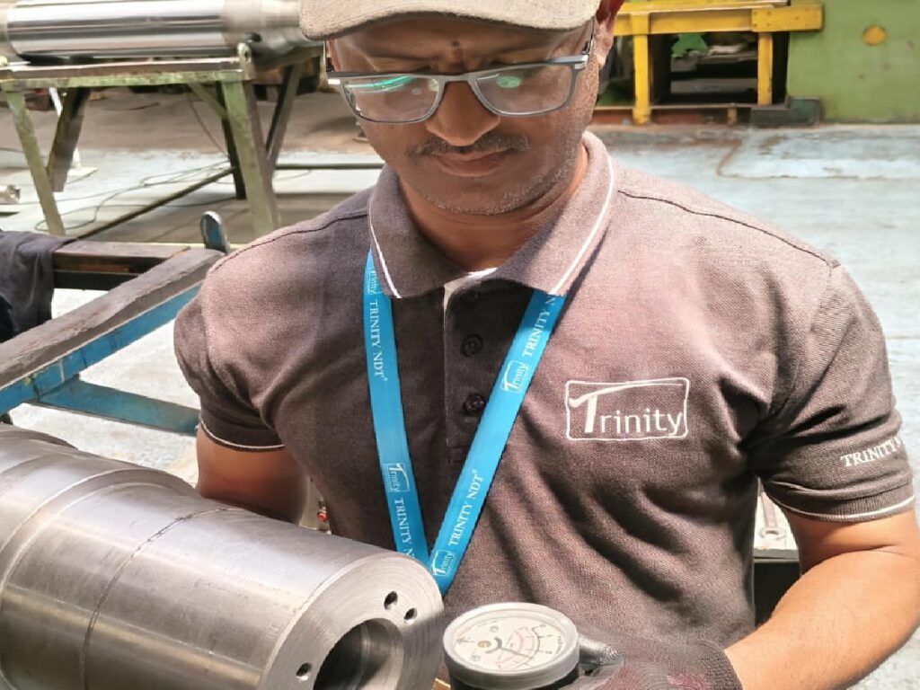
Image 2: Final residual field measurement after successful demagnetisation — below 3 Gauss. The same shaft, the same Gaussmeter probe, the same measurement location as Image 1. The residual field has been reduced to within the industry-standard acceptance limit, and the shaft is now cleared for assembly, machining, or further processing.
The comparison between Image 1 and Image 2 is the complete story of today’s job. A reading that was well above any acceptable limit, brought back to compliance through methodical technique, the right equipment, and the experience to recognise when a standard approach is not working and adapt.
The client’s shaft left our facility with a formal Demagnetisation Test Record documenting:
- Component description and identification
- Initial residual field readings (mapped at multiple points along the shaft)
- Demagnetisation method, equipment, and parameters used
- Post-demagnetisation residual field readings (verified below 3 Gauss at all points)
- Operator identification and certification
- Date and time of service
That document is the client’s proof — for their quality records, for their client, and for any regulatory or inspection body that might ask — that the demagnetisation was done correctly and was verified.
What the 3 Gauss Specification Means — And Where It Comes From
The 3 Gauss (0.3 mT) maximum residual field requirement is the most widely cited acceptance criterion in industrial demagnetisation. It appears in:
- ASTM E1444 — Standard Practice for Magnetic Particle Testing (the primary MPI standard in the USA and widely followed in India for ASME-coded work)
- AWS D1.1 — Structural Welding Code, which references maximum residual field requirements before welding repairs
- MIL-STD-1949 — Military standard for magnetic particle inspection
- NAS 410 — Aerospace NDT standard (for aerospace-grade components, residual field requirements can be stricter than 3 Gauss)
- Various OEM and end-user specifications for bearing and gear manufacturers
Some specific applications — particularly in precision bearing assemblies, compass-critical components, and aerospace rotating machinery — specify maximum residual fields of 1 Gauss or even below 0.5 Gauss. When clients bring such requirements, our demagnetisation procedure is adjusted accordingly and the verification threshold is tightened to match.
If your component’s specification does not state a residual field limit but you need demagnetisation, our default acceptance criterion is below 3 Gauss — consistent with ASTM E1444. We always record the actual achieved reading so you have the documented evidence, not just a pass/fail statement.
When Is Demagnetisation Required?
Based on the range of jobs we handle at our Peenya facility, these are the most common situations where demagnetisation is needed:
After Magnetic Particle Inspection (MPI/MPT): This is the most frequent reason. Every MPI inspection magnetises the component. If the component is going into service in a bearing, a gear train, an electrical machine, or a high-precision assembly — demagnetise before dispatch.
Before welding or hardfacing: A magnetised component causes arc blow during welding. If you are repairing a shaft, hardfacing a gear, or welding any ferromagnetic component that has been through an MPI inspection, demagnetise before welding.
Before precision machining: Swarf and chip attraction to a magnetised surface is a real problem in precision grinding and turning. Demagnetise before finish machining operations.
Before assembly into precision equipment: Electric motors, generators, turbines, compressors, and gear boxes all contain components that can be affected by residual magnetism in adjacent parts. Demagnetise before final assembly.
Before calibration or use with precision measuring instruments: If a magnetised shaft or component is to be measured with contact gauges or CMM probes, demagnetise first to ensure measurement accuracy.
The Equipment We Use — Why It Matters
Not all demagnetisation equipment is equal, and not all operators are equally skilled in using it.
Our demagnetisation facility at Peenya uses a combination of AC coil demagnetisers sized for different component geometries — from small precision parts to large shafts — and portable yoke-type demagnetisers for in-field and on-site demagnetisation of large structures and weldments.
The verification instrument is a calibrated digital Gaussmeter — not a compass or a simple field indicator, but an instrument that gives precise, quantitative residual field measurements in Gauss or milliTesla, with calibration traceable to national standards. The readings in Image 1 and Image 2 above are real Gaussmeter readings — not estimated, not guessed, not assessed by feel. Measured. Recorded. Reported.
Our demagnetisation technicians are NDT professionals — the same team that performs Magnetic Particle Testing (MPI/MPT) for our clients every day. They understand the physics of magnetism and demagnetisation not just as a procedure to follow, but as a principle they can apply intelligently when a standard approach is not producing the required result. Today proved why that depth of knowledge matters.
A Note on the MPI and Demagnetisation Relationship
One question we hear from clients: “If MPI causes residual magnetism, why do some MPI reports come without a demagnetisation service?”
The answer is: sometimes the residual field left after MPI is already below the 3 Gauss acceptance limit. Particularly when AC yoke technique is used, since AC magnetisation naturally has a partial self-demagnetising. This effect is due to the alternating nature of the field. In those cases, a separate demagnetisation step may not be necessary.
But when high-field DC magnetisation is used. Bench machines with high amperage, or prod techniques. the residual field can be substantial, as this shaft demonstrated. In those cases, a formal demagnetisation step with verified measurement is not optional. It is part of professional MPI service delivery.
At Trinity NDT, our Magnetic Particle Testing (MPI) service routinely includes a residual field check at the conclusion of the inspection. If the field is above the specified limit, our technicians proceed to demagnetisation as part of the job.Not as an afterthought or an add-on.
For components that arrive from other MPI facilities — as this shaft did today. We provide standalone demagnetisation as a specialist service. We measure, treat, verify, and document. The client leaves with both the demagnetised component and the formal test record.
Our Demagnetisation Service — What We Offer
If you have a component that needs demagnetisation. Whether it has just come through MPI, is going into assembly, or is heading for welding repair. Here is what our service includes:
Initial residual field measurement: Full mapping of the component surface before treatment. Not a single spot check, but a systematic survey at multiple points. This gives the baseline reading and identifies zones of concentrated retention.
Treatment: AC coil and/or portable yoke demagnetisation using parameters optimised for the component’s dimensions, geometry, and material. If a standard single-pass treatment is insufficient — as today’s shaft demonstrated — we adapt the approach until the result meets the specification.
Post-treatment verification: Full re-survey of the component surface with the calibrated Gaussmeter. Every measurement point recorded.
Formal Demagnetisation Test Record: Issued with every job. Contains all readings, equipment identification, operator details, treatment parameters, and final acceptance statement. Suitable for inclusion in your Material Data Report (MDR) or quality records.
On-site service available: For large structures, installed equipment, or high-volume production requirements, our technicians can come to your facility with portable demagnetisation and Gaussmeter equipment. We operate from our NDT Labs across Peenya, Bangalore, and across India.
Enquire about our Demagnetisation Service →
Also see: Magnetic Particle Testing (MPI) Services →
The Shaft Leaves. The Learning Stays.
By end of day today, the shaft that arrived carrying 10 Gauss of residual magnetism left our facility in compliance. Below 3 Gauss, verified, documented, and ready for assembly.
The client had been worried. They had an MPI certificate from the inspection facility, but when they measured the shaft on their own floor. The field reading alarmed their assembly engineer. They called us, brought the shaft in, and we sorted it.
This is exactly the kind of problem that a dedicated, experienced demagnetisation team is here to solve. Not every job goes perfectly on the first pass. The steel doesn’t care about your procedure document — it only responds to the physics. Understanding those physics, and having the patience and skill to apply the right technique until the reading drops, is what separates a professional demagnetisation service from one that hands back a still-magnetised component with a rubber stamp.
If your components carry residual magnetism — or if you are simply not sure whether they do — call us or WhatsApp us at +91 98441 29439 and we will advise you on the fastest and most cost-effective path to getting them into compliance.
About Trinity NDT WeldSolutions: Trinity NDT WeldSolutions Pvt. Ltd. is India’s NABL ISO/IEC 17025:2017 accredited and NADCAP Aerospace Merit accredited NDT laboratory at Peenya Industrial Area, Bangalore. We provide Ultrasonic Testing, Magnetic Particle Testing, Liquid Penetrant Testing, Radiographic Testing, Eddy Current Testing, Visual Testing, Positive Material Identification, Hardness Testing, Demagnetisation, Ultrasonic Cleaning, Vapour Degreasing, and advanced NDT (PAUT/TOFD). NDT Level I & II certification training since 2001. 4.8★ Google Rating | 1,200+ reviews | 45+ countries served.
📞 +91 98441 29439 | 📧 info@trinityndt.com | www.trinityndt.com | Peenya Industrial Area, Bangalore 560058